Carbon Nanostructures
Carbon nanostructures from polyacrylonitrile copolymer precursors
Carbon nanostructures from other block copolymer precursors
Carbon Materials from Precursors with Different Architectures
Carbon nanostructures from polyacrylonitrile copolymer precursors
The field of carbon structures was reenergized by the discovery of fullerenes in 1985,[1] carbon nanotubes in 1991,[2] and graphene in 2004.[3] In addition to generating tremendous interest in the fundamental properties of discrete carbon molecules and nano-objects these nano-structured carbons have found, or are expected to have, numerous commercial applications such as advanced fillers, materials for energy and gas storage, sensors and elements for molecular electronics devices. Two different strategies have been developed for the preparation of engineering carbon materials; one includes pyrolysis of organic precursors (mostly polymeric) under an inert atmosphere to yield large-scale engineering carbons and the other involves physical/chemical vapor deposition techniques that produce well-defined nanostructured carbons. Whereas techniques from the first group are applicable to large scale production, they offer very limited control over the carbon nano-structure. Techniques from the second group do allow atomic scale precision in control of the nanostructure but they are relatively expensive, have limited yield and require complex equipment.
This conundrum has been a focus of research for the group, carried out in conjunction with Professor Kowalewski’s group at CMU. A novel, low-cost route to well-defined nanostructured carbon materials based on the pyrolysis of polyacrylonitrile (PAN) block copolymer precursors containing a sacrificial block (e.g., poly(n-butyl acrylate) was developed.[4, 5] This work relies on the use of macromolecular carbon precursors, which through the process of self-assembly and directed self-assembly organize into well-defined nanoscale morphologies. After their nanostructure is fixed through chemical crosslinking, these materials are converted into porous nanocarbons with morphology resembling that of the starting material. Control over the nanoscale morphology opens the way to control of electronic structure by restricting the spatial extent of nanographitic domains. What is of particular importance, assuring their edge-on orientation of the nanographitic domains with respect to the pore walls, thus guaranteeing their accessibility. Such overall morphology makes these materials particularly suitable for energy storage, especially as electrodes for supercapacitors, where they show specific capacitances per unit area far exceeding those exhibited by conventional materials.[6]
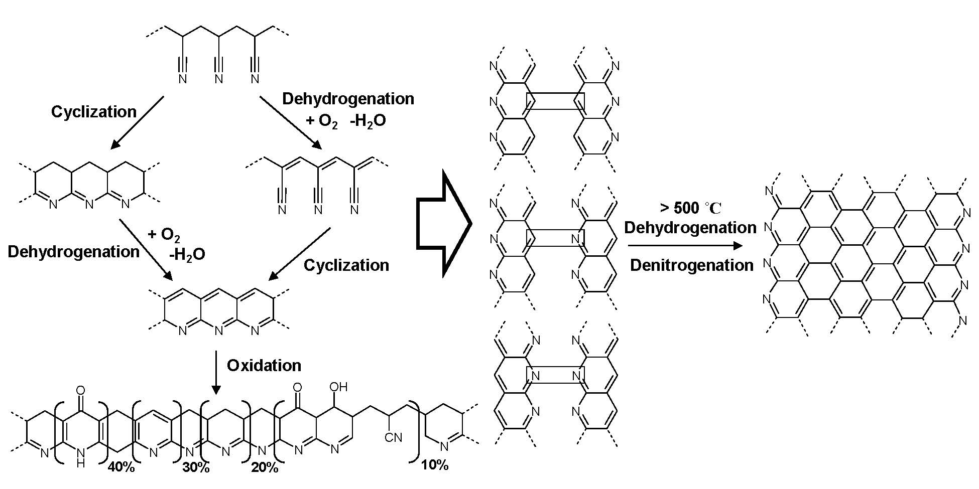
The above schematic shows the thermal chemistry of PAN carbonization: (left) thermal stabilization (right) pyrolysis which involves dehydrogenation and denitrogenation eventually leading to partially graphitic structures.
Thermal chemistry of PAN carbonization: (left) thermal stabilization (right) pyrolysis which involves dehydrogenation and denitrogenation eventually leading to partially graphitic structures. Initially the thermal stabilization occurs by crosslinking and some cyclization of PAN through heating in the presence of oxygen: temperatures between 200 oC and 300 oC. Further cyclization followed by dehydrogenation, denitrogenation and conversion to graphitic structures, upon continued heating to higher temperatures under an inert atmosphere at temperatures in excess of 500 oC. The structure of the final carbon nanostructure is templated by the initial structure of the PAN domains in the phase separated block copolymer. The PAN domains are stabilized by heating to 280 °C in the presence of air and subsequent pyrolyized by heating to 600 - 900 °C in an inert environment. This converts the PAN domains into partially graphitic carbon, whereas the sacrificial phase is volatilized. Stabilization therefore allows the PAN domains to retain their phase separated nanostructure throughout the subsequent carbonization thermal treatment.
The image of carbon nanostructures shown above (similar to the images in reference 3) is a result of the self-assembly of phase separated PAN-b-PBA block copolymer with spherical PAN domains that was prepared by ATRP and was then converted into discrete carbon nanoclusters (D~30 nm) by fixing the PAN domains through crosslinking in air and then pyrolyzing under nitrogen. The carbon structures exhibited high surface area, high thermal conductivity and have potential for catalytic activity.
When the mole fraction of the PAN is increased and a poly(BA)251-b-poly(AN)320 block copolymer is prepared and the block copolymer is cast from solution it forms cylinders or lamellae as shown below in the image on the left. When a similar block copolymer was stabilized and pyrolyzed it provided the carbon nanowires shown in the image on the right. The structures are similar to those seen in multiwalled carbon nanotubes. The carbon nanostructures are expected to find application in photovoltaics, field emitters and supercapacitors.[5]
The spectrum of carbon structures that can be prepared from PAN segmented copolymers can span the continuum from carbon nanoparticles, prepared from water soluble shell crosslinked micelles with a PAN core,[7] through lamellar structures[8] to porous carbon structures.[9-12]
In reference 8 the porous materials were prepared by using PEO-b-PAN diblock copolymers prepared by ATRP grafting from PEO macroinitiator providing block copolymers with differeing degrees of polymerization of the PAN segments from 16 to 208 resulting in a PAN content of 20-70 wt %. The segmented copolymers are suitable for use as templates for the synthesis of mesoporous silicas, since PEO is known to promote the condensation of silica under acidic conditions. The templated PAN was stabilized then pyrolyzed prior to dissolution of the silica in aqueous sodium hydroxide forming porous carbons with high surface areas, ~900 m2 g-1 and the total pore volumes were 0.9-1.9 cm3 g-1. The carbons exhibited some degree of ordering of graphene sheets in their frameworks. A clear similarity between the silica pore shape and the carbon nanostructure shape was observed for samples from the silica/EO45AN43 composite.
In the images shown above, the block copolymers were drop cast onto the substrate and the phase separated domains did not exhibit any long range order. However when precursor films were prepared by zone-casting[13] they can display long-range order. The motivation was the preparation of macroscopically aligned anisotropic carbon structures suitable for electron transport or magnetic data storage.[14]
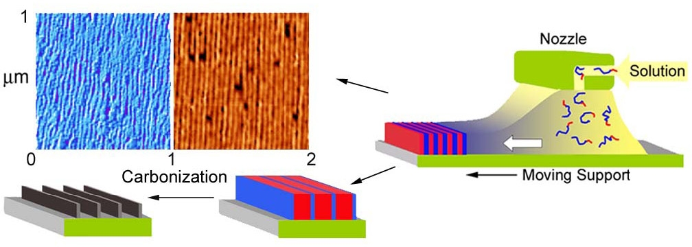
Schematic illustrating zone-casting of PBA-b-PAN block copolymers and subsequently thermal conversion into anisotropic carbon.
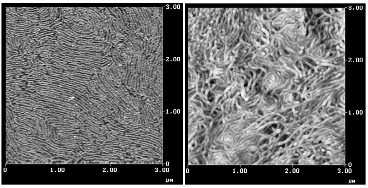
Zone casting involves deposition of a polymer solution at a controlled temperature on a moving substrate whose temperature is also controlled. The task was performed using a custom-built apparatus, equipped with two computer controlled linear stages and independently-controlled solution and substrate heaters. However after carbonization and lifting the carbon sheet from the substrate the carbon sheets collapsed, while maintaining thickness corresponding to PAN lamellae width. Other systems were examined and as shown below the direction of orientation of the domains can be controlled during casting. The upper image above shows the morphology attained when a diblock copolymer, PBA-b-PAN block copolymer, is cast from dimethylformamide solution at 90 oC. The lower images show the morphology attained when a triblock copolymer with a crystallizable segment, such a poly(tert-butyl acrylate)-b-poly(octadecyl methacrylate-b-poly(tert-butyl acrylate) (PtBA-b-PODMA-b-PtBA) is cast onto the moving substrate at two different temperatures, one below the melting point (Tm) and the other above the Tm.
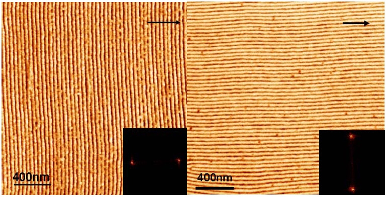
Zone-casting a PtBA-b-PODMA-b-PtBA block copolymers with crystalline segments at different casting temperature (Left: T > Tm; Right: T < Tm)
In the first case, a block copolymer with a number molecular weight of 37,500 g/mol (with the structural formula (BA)240(AN)124) and polydispersity index of 1.22 (from gel permeation chromatography (GPC)) was prepared and subjected to zone casting. The long-range ordered lamellae were perpendicular to the substrate and casting direction. Upon thermal stabilization and carbonization, the precursors were converted into anisotropic carbon with long-range order.[8] In the second case, the orientation of the nano-morphology is governed by the process of nucleation and crystallization of the crystallizable phase. The lamellar structure is aligned along the casting direction through the crystallization of the pODMA domains if the casting temperature is below melting point (Tm) of the crystallizable segments.[13] Therefore control of the advancement of solidification front provides the means to control the kinetics and degree of order in phase-separating block copolymer systems.
Earlier work on PAN carbonization focused primarily on the preservation of nanoscale morphology and on the benefits stemming from the presence of nitrogen heteroatoms originating from the polyacrylonitrile precursor and demonstration that when these copolymer-templated nitrogen-enriched porous nanocarbons (CTNC) were used as electrodes in supercapacitors, they yielded capacitances per unit surface area, i.e. geometric capacitance, several times higher than conventional porous carbons, over 30 μF/cm2 vs. ~ 10 μF/cm2. Furthermore, it was indicated that CTNCs could act as metal-free ORR catalysts or as CO2 sorbent materials.[6, 15, 16] Subsequently it was hypothesized that all these effects pointed to a synergy between the nanographitic edge heteroatoms, primarily pyridinic nitrogens, and nonbonding zigzag edge electrons. Furthermore, the high availability of pyridinic nitrogens indicated that nanographitic domains within carbon framework are oriented with their nitrogen-rich zigzag edges facing the pore walls, and that such orientation is facilitated by the molecular orientation of the self-assembled macromolecular precursors.
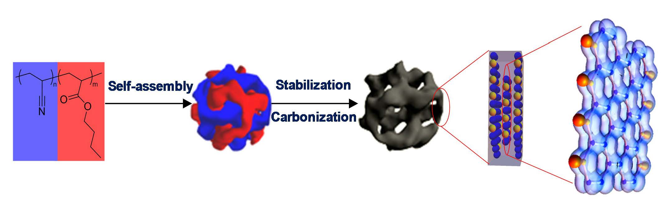
This porous material is composed of nanographene “clusters” containing stacked graphene sheets with the lateral extent of the order of 3-5 nanometers. The nitrogen functionalities or other heteroatoms originating from the carbon precursor phase play a crucial role in various applications. It was recently recognized that based on the carbonization mechanism, zig-zag (pyridinic) edge forms along the PAN chain due to cyclization and armchair edge forms via fusion among different cyclized ladder-like chains. [6]
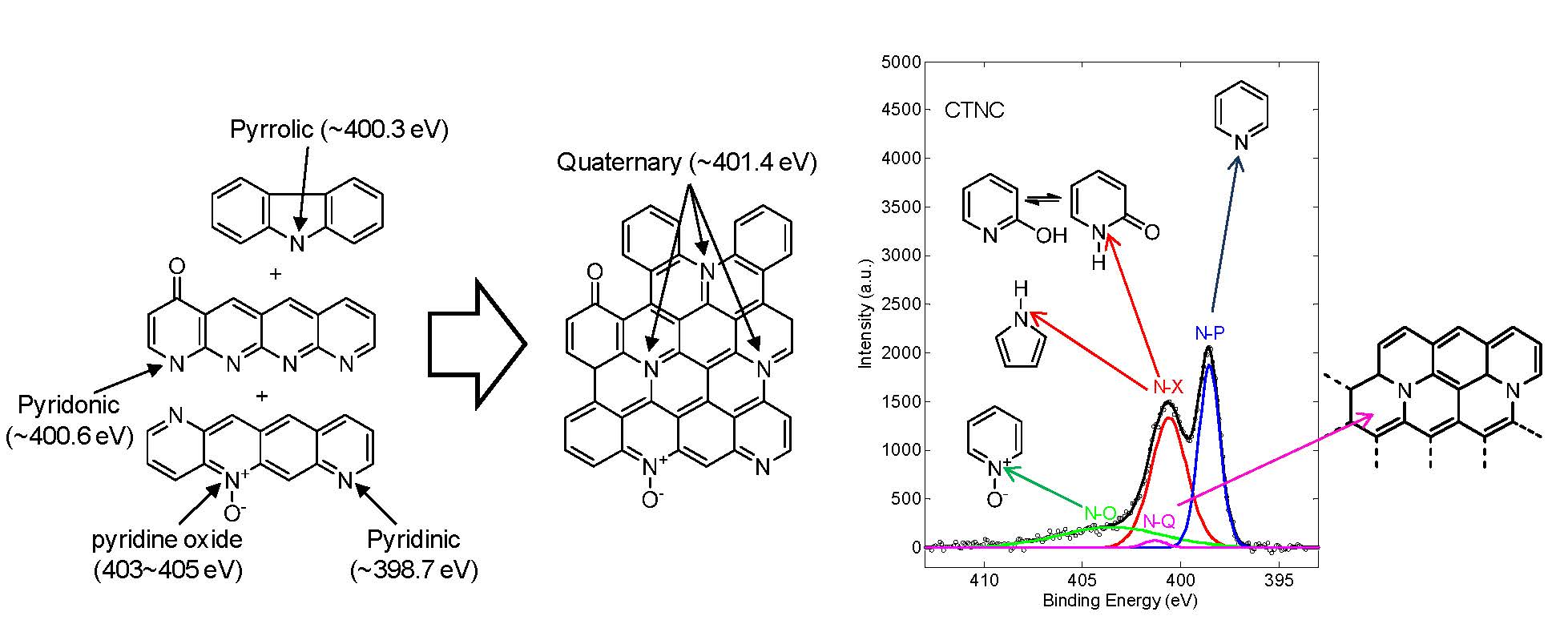
Schematic picture of pyrolysis involving a dehydrogenation, loss of pyridinic, pyrrolic, pyridonic nitrogen atoms, and the formation of quaternary nitrogen atoms.
The N 1s peak in the X-ray photoelectron spectrum (XPS) of one of the CTNC prepared for in this series is shown above, the sample pyrolized at 700 °C, and points to the presence of three major nitrogen species differentiated by their binding energies (BE); (i) pyridinic (N-P, BE ≈ 398.5 eV), (ii) mixture of pyridonic (N-X, BE ≈ 400.6 eV) and pyrrolic (BE ≈ 400.3 eV), and (iii) pyridine oxide (N-O, BE ≈ 403 - 405 eV).[17] The chemical environments of these nitrogen atoms revealed by XPS, 35% pyridinic, 43% pyridonic + pyrrolic, and 20% pyridine oxide, are consistent with their proposed location along the outer edges of accessible nanographitic domains. In addition to those “edge” nitrogens, the spectrum shown above, also indicated the presence of a relatively small fraction (2%) of basal quaternary nitrogen species (N-Q, BE = 401.4 eV).
It was determined that the presence of nitrogen heteroatoms in the copolymer-templated nitrogen-enriched porous nanocarbons (CTNCs) which had previously been successfully used as electrode materials for supercapacitors and electrocatalysts for the oxygen reduction reaction (ORR) [6, 15] that both the nitrogen content and surface area are influenced by pyrolysis temperature [16] and performance in specific applications is significantly enhanced by the presence and composition of the accessible nitrogen functionalities. The electron-withdrawing nature of these nitrogen atoms, owing to their electronegativity compared to carbon, results in a lowering of electron density for neighboring carbons. Such replacement of C with N could change their electronic structures, leading to the formation of active edge-site regions, and thus, multifunctional electronic applications including ORR, HER and CO2 reduction/capture.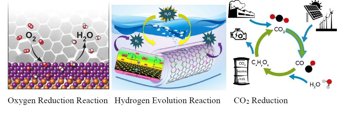
Carbon nanostructures from other block copolymer precursors
Since carbon nanographitic structures derived from PAN precursors can contain up to 7% nitrogen, which results in defect sites that affect electronic properties we additionally determined if carbon materials can be prepared from non-PAN-containing polymers. Poly(vinyl acetylene) is a polymer that structurally resembles PAN without an inherent nitrogen group and could possess the potential to form similar nanostructured carbon materials without the presence of preformed n-type dopants, Therefore poly(vinyl acetylene) block copolymers were prepared and evaluated as carbon precursors.[18] The active acetylenic hydrogen atom in vinylacetylene was substituted with the trimethylsilyl group in order to prevent 1,4-polymerization and Cu(I)-catalyzed coupling reactions and provided a well-controlled homopolymerization using ATRP.
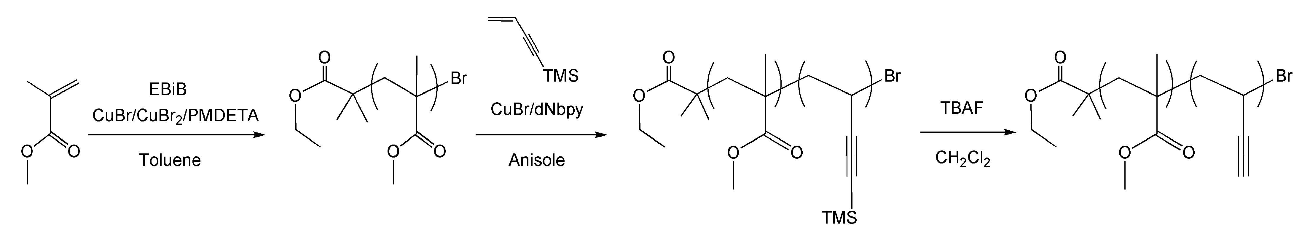
Block copolymers were prepared using PMMA macroinitiators and it was determined that ARGET ATRP at lower temperatures provided additional control over the chain extension reactions.
Polystyrene crosslinked under UV-irradiation will also pyrolyze at elevated temperatures and result in semi-graphitic carbon materials. Both amphiphilic block copolymers that micellize in water (PEO-b-PS) and brushes with PMMA backbones and PS-b-PAA side chains were used to template these nanocarbon structures.[19] [20] Well-defined nanostructured carbon was prepared by pyrolysis of core cross-linked micelles formed from block copolymers containing polystyrene segments.
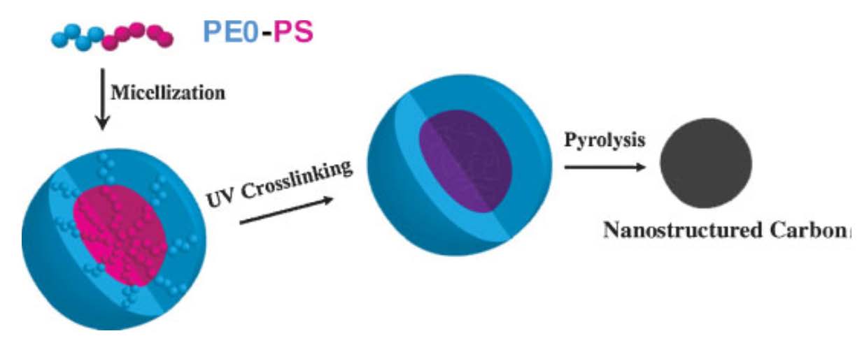
These micelles were obtained by self-assembly of poly(ethylene oxide)-block-polystyrene (PEO113-b-PS52) diblock copolymer or brush macromolecules containing polymethacrylate backbone and side chains with PS and poly(acrylic acid) block segments (PBPEM330-g-PS40-b-PAA111) in selective solvents. UV irradiation was used to induce crosslinking of the PS core in the micelles. After pyrolysis, the cross-linked PS cores were converted to a partially graphitic carbon, while the shells were sacrificed, resulting in the formation of discrete carbon nanoobjects. The formation of carbon material was confirmed by Raman scattering spectroscopy while the morphology of the precursor and the resulting pyrolyzed product was studied by at AFM.
Carbon Materials from Precursors with Different Architectures
Other materials containing PAN with different architectures can be used as the sacrificial phase to prepare nano-structured carbon. Nano-porous carbon with high surface area was prepared by conducting a grafting from polymerization of acrylonitrile from the surface of silica nanoparticles by ATRP. The (PAN)-grafted silica nanoparticles were cast into a film, stabilized, carbonized and then etched to form highly nanoporous carbon films. The motivation was the preparation of a carbon membrane suitable for gas adsorption, filtration and separation or use in photovoltaic cells. The TEM image clearly shows that a well-structured material was prepared.[8-11]
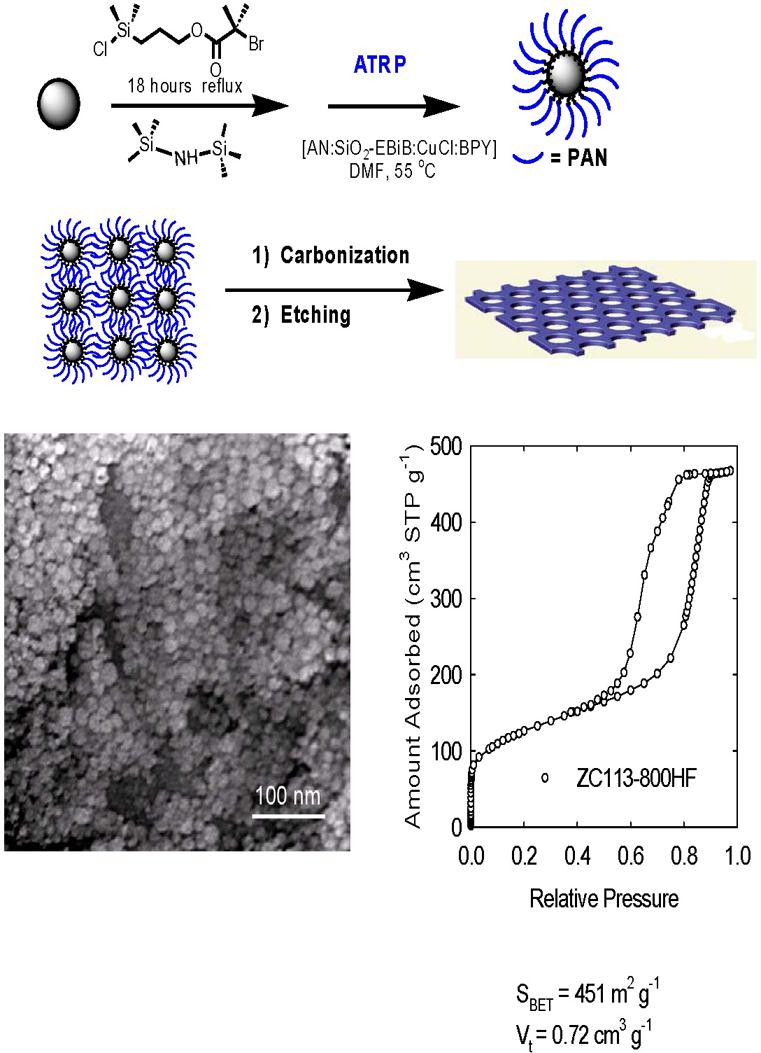
The high-temperature treatment led to a marked enhancement of graphitic ordering, which manifested itself in a narrowing of wide-angle XRD peaks, and in the appearance of domains of lateral dimensions 5-15 nm, consisting of stacked graphitic planes with interplanar spacing of approximately.0.34 nm spacing. Raman spectroscopy provided evidence for the increased content of graphitic sp2 carbon structures. The structure had the capacity to adsorb a significant volume of nitrogen. The specific surface areas and total pore volumes of the carbons were as high as 500-600 m2 g-1 and 0.8-1.8 cm3 g-1, respectively.
Nanoporous carbon materials containing heteroatoms are important for various applications. One potential precursor for nitrogen-doped carbons is poly(4-cyanotstyrene) (P(4-CNSt)). Novel carbon precursors containing cyano groups were prepared by grafting 4-cyanostyrene from silica particles by surface-initiated atom transfer radical polymerization.[21] The poly(4-cyanostyrene) grafted silica particles were cross-linked via the Pinner reaction to form tetrazine crosslinking units. The cross-linked nanoparticles exhibit intra- and interparticle cross-linking, as confirmed by dynamic light scattering and scanning electron microscope analysis. The cross-linked samples were then carbonized at 800 °C for 3 h under an inert atmosphere to form C-x-SiO2(y)-g-P(4CNSt). The initial low surface areas (SBET ≈ 20 m2 g-1) were dramatically increased (SBET ≈ 350–485 m2 g-1) upon carbonization. Etching the silica particles with HF further increased the surface areas yielding a 3D-interconnected network of nitrogen-doped nanocarbons with surface areas exceeding 750 m2 g−1. The particles were characterized by XPS and combustion analysis. The surface nitrogen functional groups were identified by the deconvolution of high-resolution N 1s spectra. The complex N 1s spectra can be deconvoluted into four different types of nitrogen species, that is, pyridinic (N-6), pyridonic (N-X), quaternary (N-Q), and pyridine oxide (N-O). The percentage of N-Q was relatively higher compared to other three types of nitrogen species. These N-doped nanocarbons are interesting materials to investigate for use in various electrochemical applications due to their high surface area and good interconnectivity.
In 2017 a novel procedure that provided a facile aqueous route to nitrogen-doped mesoporous carbons with very high surface area was developed. This procedure exploited the fact that it was shown that the addition of zinc chloride enabled the solubilization of low molecular weight PAN in an aqueous dispersion of porogenic fillers such as commercially available Ludox SiO2 colloids of nano-cellulose which allowed subsequent fabrication of highly porous carbons.[22] This was accomplished as the ZnCl2 serves as a solubility enhancing porogen (i.e. one displaying concurrent hard templating and electrolyte evaporation). Pure ZnCl2 has a boiling point ~ 732 °C however in the ZnCl2 /PAN system, ZnCl2 completely volatilized ~550 °C, which allows for complete removal of the salt during pyrolysis above 600 °C. So the procedure is environmental friendly (aqueous system) generating carbons with high surface area (~1776 m2/g) and high nitrogen content (9.9 wt%). Samples were prepared by freeze drying the initial composite solutions prior to carbonization. The process was also extended to organic media including commercial cellulose nanocrystals (1366 m2/g) and cellulose filter paper (1501 m2/g) as templates to prepare nanoporous carbons. Interestingly, carbonization of filter paper infiltrated with PAN/ZnCl2 solution allowed fabrication of free-standing, monolithic NPC films indicating that the cosolubilization approach has general applicability to all-organic systems.
Another approach to preparation of individual porous carbon spherical structures was also developed in 2017.[23] The process enabled the scalable synthesis of dispersed NPC-S materials by coating sacrificial protective layers around polyacrylonitrile nanoparticles (PAN NPs) to prevent interparticle cross-linking during carbonization. The polyacrylonitrile nanoparticles were synthesized using miniemulsion polymerization, followed by grafting of 3-(triethoxysilyl)propyl methacrylate (TESPMA) to form well-defined core−shell structured PAN@PTESPMA nanospheres. The cross-linked PTESPMA brush layer suppresses cross-linking reactions during carbonization at 700 0C under N2 and after etching of the protective silica shell uniform NPC-S exhibiting diameters of ∼100 nm, with relatively high accessible surface area (∼424 m2/g), and high nitrogen content (14.8 wt %) were obtained.
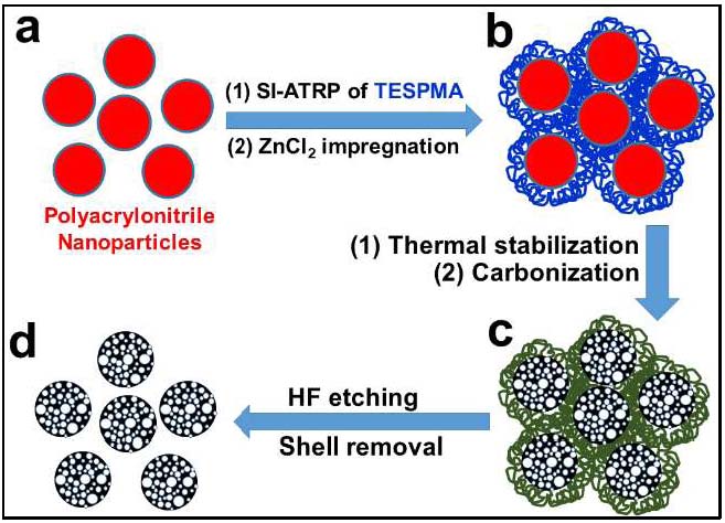
When compared to a regular nanoporous carbon monolith (NPC-M), the nitrogen-doped NPC-S demonstrated better performance for CO2 capture with a higher CO2/N2 selectivity, and increased efficiency in catalytic oxygen reduction reactions, as well as improved electrochemical capacitive behavior. This miniemulsion polymerization-based strategy for the preparation of functional PAN NPs provides a new, facile approach to prepare high performance porous carbon spheres for diverse applications. The porous carbon particles exhibited superior adsorption capacity; better selectivity for CO2 capture manifested by the ~20:1 ratio of adsorbed CO2 over N2. The NPC-S are effective catalysts in ORR via a four-electron mechanism and act as high-performance supercapacitors. The significant increase in the performance of electrocatalytic NPC-S and CO2-adsorption performance of NPC-S, in conjunction with the economic viability of the miniemulsion, make the presented method a promising alternative for the viable development of carbon nanomaterial-based technologies.
Densely grafted brushes molecules
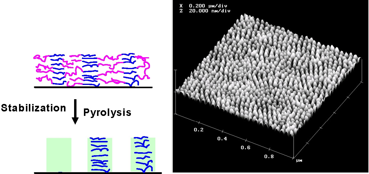
Well defined carbon structures were also prepared from densely grafted brushes molecules with polyacrylonitrile (PAN) di-(AB) and triblock-(ABC) copolymer side chains were prepared by a grafting from technique.[14] Tapping-mode AFM showed that these brushes displayed wormlike shapes on mica surface. A necklacelike structure was observed for brushes with poly(butylacrylate)-b-polyacrylonitrile-b-poly(tert-butylacrylate) triblock copolymer side chains. After conversion of poly(tert-butylacrylate) side chains to poly(acrylic acid), they were cross-linked with a diamine to fix the extended 3-dimensional structure. Such shell-cross-linked molecular brushes showed improved stability during transferring from solution to flat substrates and have been successfully converted into nanostructured carbons through pyrolysis. The pyrolyzed materials exhibited characteristics of partially graphitic carbon.
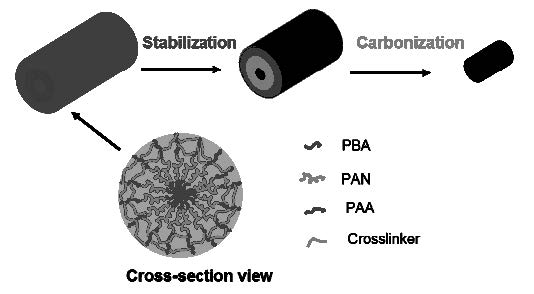
Schematic showing conversion of shell crosslinked brushes into nanostructured carbons.
Thin films of the SC brushes were prepared by drop casting aqueous solutions onto clean silicon wafer substrates and showed increased shape persistence when transferred from solution to substrates, which was demonstrated by the significant increase of their height in comparison to brushes without shell cross-linking. The samples were then subjected to annealing at 250 °C in the presence of air in order to stabilize PAN domains, and subsequently pyrolyzed at 600 °C under N2 flow. After thermal treatment, SC brush precursors were converted into nanostructured carbon. AFM images of such films revealed a surface with characteristic round protrusions and rms roughness of 4.0 nm. Such morphology was consistent with the film composed of well-defined, discrete nano-objects.
Brush copolymers with the reverse composition of the arms, in this case –PBA-b-PAN were prepared using the “grafting from” approach and upon carbonization of the PAN block (DP was varied from 29-180) and decomposition of the PBA block (DP = 41-45 in all samples) these bottlebrush precursors formed mesoporous nitrogen-doped nanocarbons as a consequence of the interpenetration of the PAN-segments on the arms of the bottlebrush macromolecules. Therefore was necessary to ensure that the DP of the PAN segments was sufficiently high to prevent collapse of the mesoporous carbons.
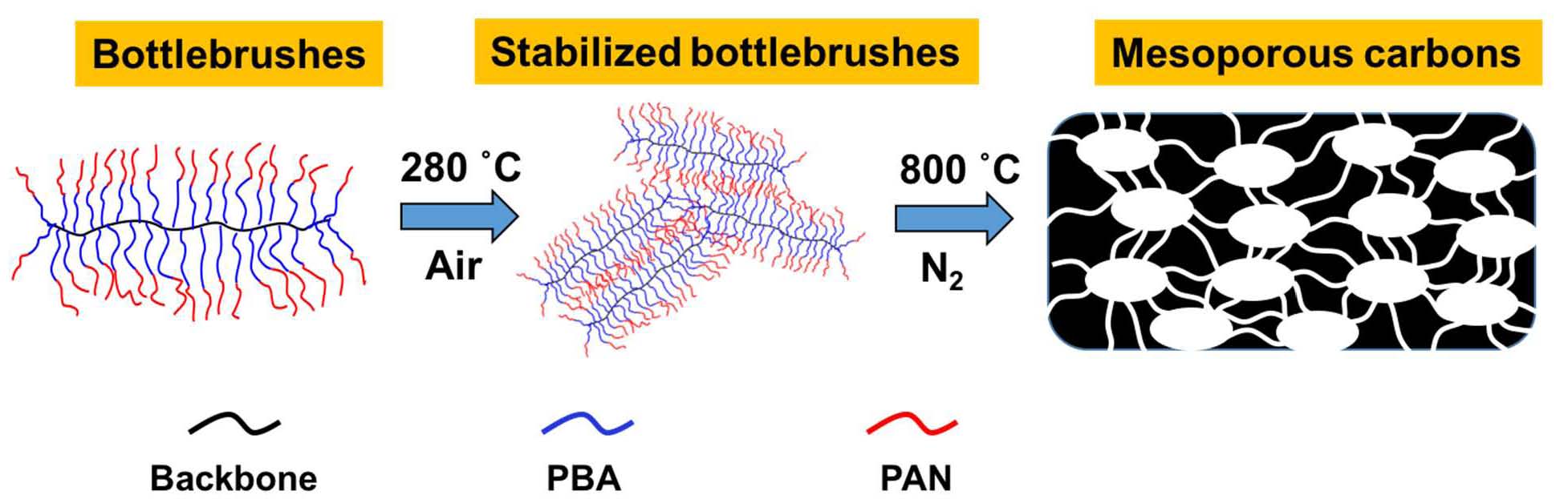
In the case where extensive intermolecular crosslinking were established the resulting nano-structured carbons displayed similar pose size distribution (PSD) regardless of the PD of the PAN segments or the backbone of the brush. The specific surface area (SSA) was dependent of the DP of the PAN segments and was as high as 420 m2/g for the sample with DP of the PAN = 180.[24] The electrochemical properties of the formed N-doped carbon derived from sample L56–g-BA45-b-AN114 was then used to test ORR activity because of its relatively large mesoporous surface area. The carbon powder, ground with mortar and pestle was dispersed in an ethanol solution containing Nafion as a binder and deposited on a GC electrode. Then it was used as a working electrode in a standard three electrode setup to measure its potential activity for an oxygen reduction reaction (ORR). Through comparison between cyclic voltammetry (CV) curves obtained in 0.1 M KOH solutions saturated with Ar and O2, a clear reduction peak observed in the latter case, with a low onset overpotential (ήos = 0:87 V vs. RHE) provided initial evidence of good ORR performance for the sample. This onset potential was more positive compared with electrodes prepared in the same fashion (namely, using Nafion binder) from linear PBA-b-PAN BCPs shown in our previous work (ήos = 0:81 V vs. RHE).[25] The achieved current density was higher in BCP-templated nanocarbons since the BCPs were pyrolyzed at 700 C, manifesting a lower degree of graphitization, such increased current density was most likely due to a higher nitrogen content. Linear sweep voltammograms (LSV) were then recorded using a rotating disk electrode (RDE) to evaluate the kinetics of the ORR and showed increasing current density with faster rotation. Koutecky-Levich (K-L) analysis of the polarization curves was employed in order to determine the number of electrons transferred in ORR. Generally, ORR can occur via either two or four-electron transfer mechanism, the former leading to the formation of H2O2 and the latter directly to OH, which is desirable in fuel cells.
A similar study was conducted with an ATRP grafting from the surface of silica particles to prepare SiO2-g-poly(styrene-co-acrylonitrile) (PSAN).[26] The advantage of forming tethered PSAN chains is that after peroxidation and carbonization is that a novel type of nanoporous carbon is formed with well-distributed uniform spherical mesopores as well as possessing microporous carbon walls due to the loss of thermally decomposable styrene units. The micropores were mainly sized at 0.5 and 1.4 nm based on DFT calculations.
As a further extension of the work on the preparation of porous polymers with designed pore structure, macropores were introduced into a unique polymeric network by conducting intra/interbrush crosslinking of polystyrene side chains present on well-defined bottlebrush molecules.[27]
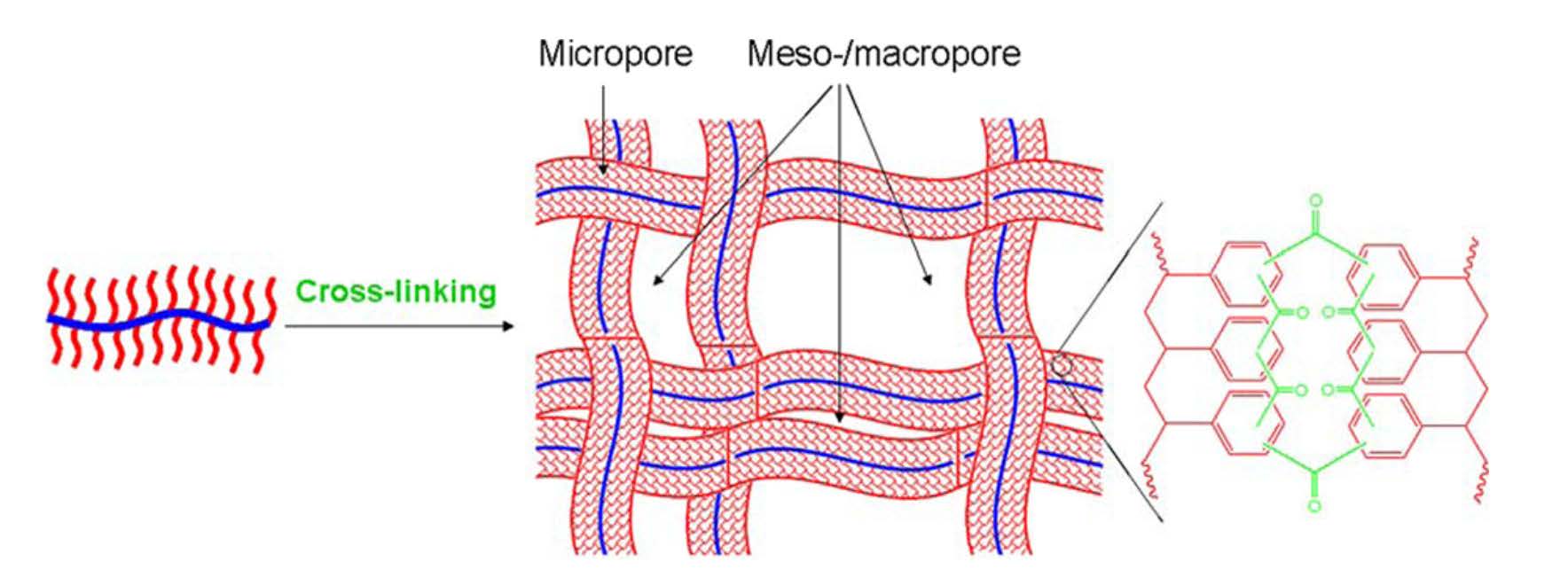
The size of the side chains plays a vital role in the tuning of nanostructure of networks at the molecular level. We also show that the as-prepared polymeric nanoscale networks exhibit high specific adsorption capacity per unit surface area because of the synergistic effect of their unique hierarchical porous structures. This strategy represents a new avenue for designing the network unit topology and provides a new application for molecular bottlebrushes in nanotechnology.
Another approach to nanoporous carbons, in this case with more regular sized mesopores was discussed in the following reference.[29]
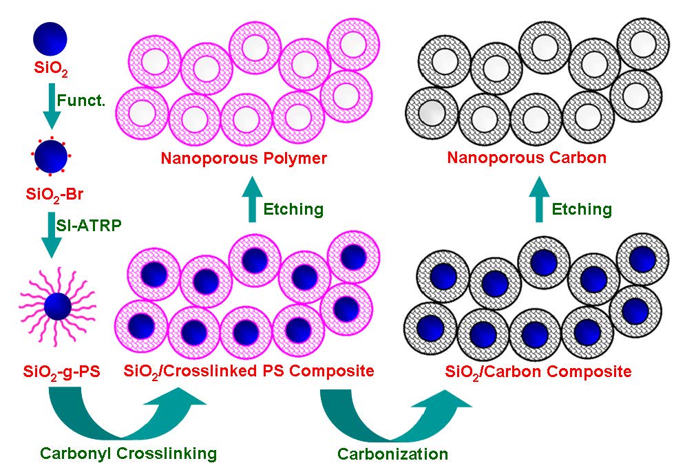
The final NPNs contain three types of pores: (i) micropores induced by cross-linking of the hairy polystyrene shell, (ii) mesopores obtained by removal of sacrificial silica nanoparticle core, and (iii) meso-/macroporous network formed through interparticle cross-linking. Use of the unique, well-defined, core-shell network unit could afford the nanomaterials with advanced responsive properties and superior performance as storage/release matrices. In addition to the well-developed microporosity, the polystyrene-based framework opens the way to further functionalization and customization of surface chemistry.
Similar to the process for the formation of super-hierarchical carbons from polystyrene bottlebrush macromolecules the aggregated hybrid particles observed in a film of the SiO2-g-PS nanoparticles retain a well-defined spherical shape with average size of about 18 nm and aggregate with each other in various directions. Such aggregation facilitates the interparticle cross-linking during the subsequent Friedel-Crafts achieved by placing the SiO2-g-PS films into a heated (75 0C) mixture of anhydrous aluminum chloride and carbon tetrachloride for 20 h under stirring. The -CCl2- cross-linking bridges were subsequently converted into the –CO- ones by hydrolysis in the presence of water. Such-CO- bridges are essential for efficient carbonization of the PS framework and inheritability of the nanostructure during carbonization.
Novel nanoporous materials of this kind hold considerable promise in applications as electrode materials in supercapacitors and fuel cells, as controlled drug delivery systems, advanced catalyst supports, CO2 capture materials, and as HPLC packing materials.
A facile aqueous route to nitrogen-doped mesoporous carbons with high SSA and high nitrogen content was recently developed. [30] The procedure is a scalable synthesis applicable to the preparation of nitrogen-doped porous carbons with high specific surface area (SSA) and high nitrogen content. Low molecular weight polyacrylonitrile was solubilized in water in the presence of ZnCl2 that also acted as a volatile porogen during PAN pyrolysis to form mesoporous structures with significantly increased SSA by templating with commercial SiO2 nanoparticles, nanocellulose fillers or filter paper to form nanocarbons with SSA = 1776, 1366, and 1501 m2/g, respectively and 10 wt % N content.
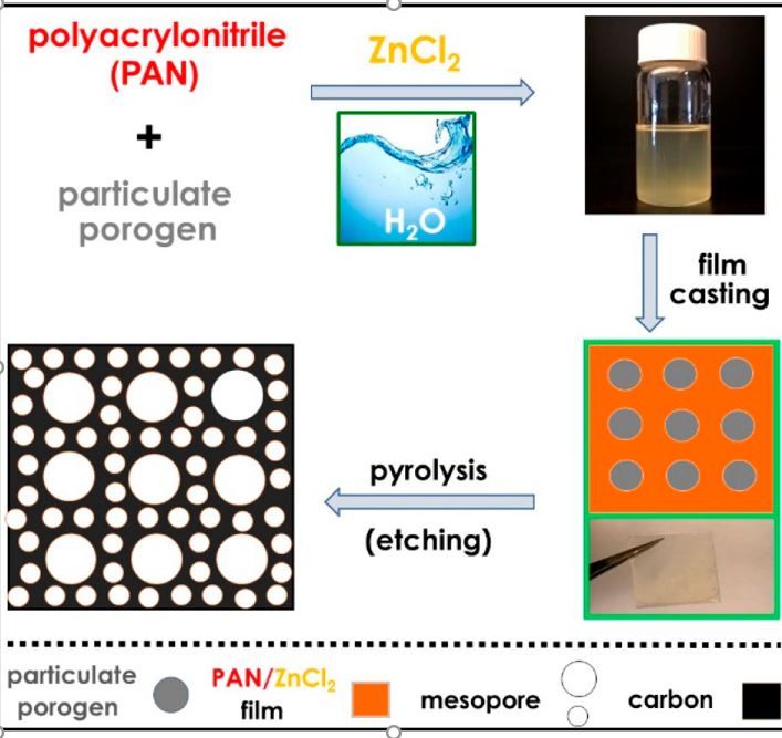
ZnCl2 serves as a solubility enhancing porogen (concurrent hard templating and electrolyte evaporation), while pure ZnCl2 has a boiling point ~ 732 °C, in the ZnCl2 /PAN system, ZnCl2 completely volatilized ~550 °C, which allows for complete removal of the salt during pyrolysis above 600 °C thereby allowing retention of high mole fraction of N- in the final carbon structures. It was determined that the cumulative effect of ZnCl2 volatilization and PAN carbonization determines the final size of mesopores.
Transmission electron microscopy (TEM) revealed the increase of the density of micropores with SiO2 content as well as the more anisotropic pore structure of the cellulose-derived NPCs. Interestingly, carbonization of filter paper infiltrated with PAN/ZnCl2 solution allowed fabrication of free-standing, monolithic NPC films. Respective atomic contents of carbon, nitrogen, and oxygen were found to be 84.0%, 9.6%, and 4.9%.
The ratios of different nitrogen types are 21.7% (pyridinic-N), 56.7% (pyridonic- or pyrrolic-N), and 21.6% (pyridine oxide-N). Furthermore, the full width at half maximum of the N−P peak was only 1.4 eV. This is significantly less than previously reported values for pyridinic nitrogen in pyrolytic carbons derived from PAN, demonstrating the high degree of uniformity of NPCs.
The electrocatalytic activity of prepared carbons showed excellent catalytic activity toward ORR via the four-electron mechanism.
REFERENCES1. Kroto, H.W., et al., C60: buckminsterfullerene. Nature, 1985. 318(6042): p. 162-3.
2. Iijima, S., Helical microtubules of graphitic carbon. Nature, 1991. 354(6348): p. 56-8.
3. Novoselov, K.S., et al., Electric Field Effect in Atomically Thin Carbon Films. Science (Washington, DC, U. S.), 2004. 306(5696): p. 666-669.
4. Kowalewski, T., N.V. Tsarevsky, and K. Matyjaszewski, Nanostructured Carbon Arrays from Block Copolymers of Polyacrylonitrile. J. Am. Chem. Soc., 2002. 124(36): p. 10632-10633.
5. Kowalewski, T., R.D. McCullough, and K. Matyjaszewski, Complex nanostructured materials from segmented copolymers prepared by ATRP. European Physical Journal E: Soft Matter, 2003. 10(1): p. 5-16.
6. McGann, J.P., et al., Block Copolymer Templating as a Path to Porous Nanostructured Carbons with Highly Accessible Nitrogens for Enhanced (Electro)chemical Performance. Macromol. Chem. Phys., 2012. 213(10-11): p. 1078-1090.
7. Tang, C., et al., Well-defined carbon nanoparticles prepared from water-soluble shell cross-linked micelles that contain polyacrylnitrile cores. Angewandte Chemie, International Edition, 2004. 43(21): p. 2783-2787.
8. Tang, C., et al., Long-Range Ordered Thin Films of Block Copolymers Prepared by Zone-Casting and Their Thermal Conversion into Ordered Nanostructured Carbon. Journal of the American Chemical Society, 2005. 127(19): p. 6918-6919.
9. Kruk, M., et al., Well-Defined Poly(ethylene oxide)-Polyacrylonitrile Diblock Copolymers as Templates for Mesoporous Silicas and Precursors for Mesoporous Carbons. Chemistry of Materials, 2006. 18(6): p. 1417-1424.
10. Kruk, M., et al., Synthesis of Mesoporous Carbons Using Ordered and Disordered Mesoporous Silica Templates and Polyacrylonitrile as Carbon Precursor. Journal of Physical Chemistry B, 2005. 109(19): p. 9216-9225.
11. Kruk, M., et al., Partially graphitic, high-surface-area mesoporous carbons from polyacrylonitrile templated by ordered and disordered mesoporous silicas. Microporous Mesoporous Mater., 2007. 102(1-3): p. 178-187.
12. Kowalewski, T., et al., Advances in nanostructured carbons from block copolymers prepared by controlled radical polymerization techniques. ACS Symposium Series, 2006. 944(Controlled/Living Radical Polymerization): p. 295-310.
13. Wu, W., K. Matyjaszewski, and T. Kowalewski, Monitoring Surface Thermal Transitions of ABA Triblock Copolymers with Crystalline Segments Using Phase Contrast Tapping Mode Atomic Force Microscopy. Langmuir, 2005. 21(4): p. 1143-1148.
14. Tang, C., et al., Synthesis and Morphology of Molecular Brushes with Polyacrylonitrile Block Copolymer Side Chains and Their Conversion into Nanostructured Carbons. Macromolecules, 2007. 40(17): p. 6199-6205.
15. Zhong, M., et al., Electrochemically Active Nitrogen-Enriched Nanocarbons with Well-Defined Morphology Synthesized by Pyrolysis of Self-Assembled Block Copolymer. J. Am. Chem. Soc., 2012. 134(36): p. 14846-14857.
16. Zhong, M., et al., Copolymer-templated nitrogen-enriched porous nanocarbons for CO2 capture. Chem. Commun. (Cambridge, U. K.), 2012. 48(94): p. 11516-11518.
17. Pels, J.R., et al., Evolution of nitrogen functionalities in carbonaceous materials during pyrolysis. Carbon, 1995. 33(11): p. 1641-53.
18. Aimi, J., L.A. McCullough, and K. Matyjaszewski, Synthesis of Poly(vinylacetylene) Block Copolymers by Atom Transfer Radical Polymerization. Macromolecules, 2008. 41(24): p. 9522-9524.
19. Burda, L., et al., Highly anisotropic conductive materials: polymers doped with crystalline charge-transfer complexes. Journal of Physics D: Applied Physics, 1983. 16(9): p. 1737-40.
20. Huang, J., et al., A novel route for the preparation of discrete nanostructured carbons from block copolymers with polystyrene segments. Macromol. Chem. Phys., 2007. 208(21): p. 2312-2320.
21. Lamson, M.; Chen, L.; Zhong, M.; Wu, D.; Matyjaszewski, K., Nitrogen-Doped Nanocarbons Derived from Tetrazine Cross-Linked Poly(4-cyanostyrene)-Silica Hybrids. Macromol. Chem. Phys. 2017, 2018, 1600524.
22. Zhang, J., et al., Facile Aqueous Route to Nitrogen-Doped Mesoporous Carbons. J. Am. Chem. Soc. 2017, 139 (37), 1293.
23. Zhang, J. et al., Individual Nanoporous Carbon Spheres (NCP-S) with High Nitrogen Content from Polyacrylonitrile Nanoparticles with Sacrificial Protective Layers. ACS Applied Materials & Interfaces 2017, 9 (43), 37804-37812.
24. Yuan, R.; Kopec, M.; Xie, G.; Gottlieb, E.; Mohin, J. W.; Wang, Z.; Lamson, M.; Kowalewski, T.; Matyjaszewski, K., Mesoporous nitrogen-doped carbons from PAN-based molecular bottlebrushes. Polymer 2017, 126 (22), 352-359.
25. Zhong, M., et al., Block copolymer-templated nitrogen-enriched nanocarbons with morphology-dependent electrocatalytic activity for oxygen reduction. Chemical Science 2014, 5 (8), 3315-3319.
26. Wu, D., et al., Novel Nanoporous Carbons from Well-Defined Poly(styrene-co-acrylonitrile)-Grafted Silica Nanoparticles. Chem. Mater., 2011. 23(8): p. 2024-2026.
27. Liang, Y.; Chen, L.; Zhuang, D.; Liu, H.; Fu, R.; Zhang, M.; Wu, D.; Matyjaszewski, K., Fabrication and nanostructure control of super-hierarchical carbon materials from heterogeneous bottlebrushes. Chemical Science 2017, 8 (3), 2101-2106.
28. Wu, D., et al., Preparation of Polymeric Nanoscale Networks from Cylindrical Molecular Bottlebrushes. ACS Nano, 2012. 6(7): p. 6208-6214.
29. Wu, D., et al., Nanoporous Polystyrene and Carbon Materials with Core-Shell Nanosphere-Interconnected Network Structure. Macromolecules, 2011. 44(15): p. 5846-5849.
30. Zhang, J., et al., Facile Aqueous Route to Nitrogen-Doped Mesoporous Carbons. J. Am. Chem. Soc. 2017, 139 (37), 12931-12934.